- Use a PCB CNC machine when you need fast iteration: prototypes can be produced in hours or days rather than the 2 to 4 weeks common with standard outsourcing.
- PCB CNC machines primarily do subtractive manufacturing on copper-clad laminates: drilling, isolation milling, routing, and engraving.
- Consistent results depend heavily on setup: flatness, zeroing, tool length reference, and stable workholding matter as much as the machine itself.
- Most desktop PCB CNC workflows are best for 1 to 2 layer boards and usually cannot make plated through-holes (PTH) without additional plating processes.
- Plan for total cost of ownership: tooling wear, dust collection, software, maintenance, and training can outweigh the initial machine price over time.
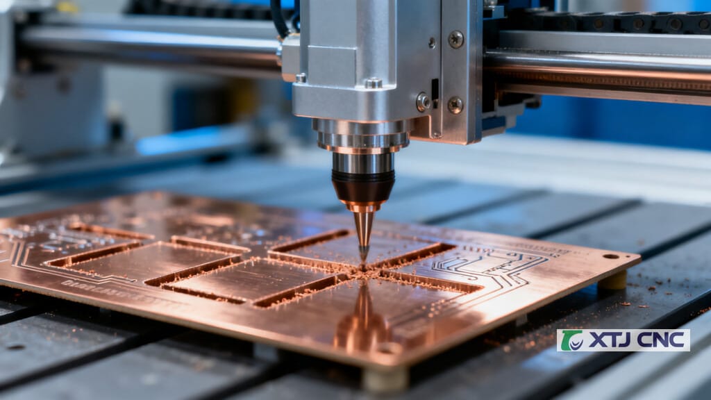
A PCB CNC machine is one of the fastest ways to turn a digital circuit-board design into a real, usable prototype without waiting on an outside fabrication house. Instead of using photolithography and chemical etching, it uses computer-controlled cutting tools to remove copper (and sometimes substrate) from a copper-clad laminate, drill holes, and route the board to its final shape.
That “in-house, same-day board” capability is a big reason PCB CNC machines are common in rapid prototyping workflows. And as PCB demand climbs with AI hardware, electric vehicles, automotive electronics, high-frequency (5G/radar) systems, and advanced packaging, precision fabrication tools continue to matter. For context, the PCB milling machine market was valued at about USD 568.3M in 2025 and is projected to reach USD 608.1M in 2026. The broader global PCB industry is projected around USD 89 to 91B in 2025 and expected to exceed USD 95B in 2026.
What Is a PCB CNC Machine? (Printed Circuit Board Computer Numerical Control Machine)
A PCB CNC machine is a computer-controlled machine tool that fabricates printed circuit boards by executing toolpaths derived from a digital PCB design. In practical terms, it “interprets” your PCB layout and converts it into physical machining actions such as:
- drilling holes
- isolation milling to create electrical separation between copper features
- routing the PCB outline (and cutouts/slots)
- engraving reference marks and identifiers
Most PCB CNC work is subtractive manufacturing performed on copper-clad laminates: the machine removes copper and/or substrate to form traces, pads, holes, and the final perimeter. CNC control improves repeatability and reduces manual error because the machine follows pre-programmed code, commonly G-code for motion and M-codes for auxiliary machine functions (spindle start/stop, coolant behavior, tool-change behaviors depending on the controller).
Because you can go from design file to physical board in-house, PCB CNC machines are widely used for rapid prototyping, when iteration speed matters more than mass-production economics.
Core Definitions: PCB, CNC, and What “PCB CNC Machine” Means
PCB (Printed Circuit Board)
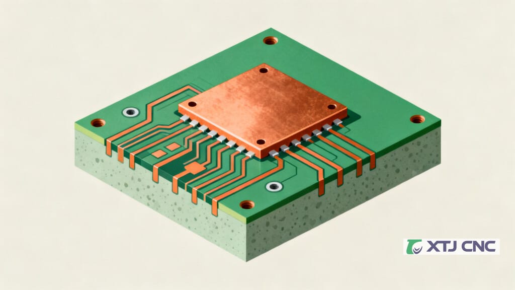
A PCB mechanically supports and electrically connects electronic components using conductive pathways (traces). Copper patterns form the “wiring,” while the substrate provides structure and electrical insulation.
CNC (Computer Numerical Control)
CNC refers to machine tools controlled by pre-programmed computer code. Instead of manual handwheels and operator-controlled cutting, a CNC system drives the machine along programmed paths with controlled feed rates, spindle speed, and depth.
CNC’s major value is repeatability: once a process is controlled, the machine can produce the same geometry repeatedly with minimal variance.
So what does “PCB CNC machine” mean?
A PCB CNC machine combines PCB fabrication needs with CNC motion control. It takes CAD/CAM output and turns it into toolpaths such as:
- isolation paths around traces and pads
- drill hits for holes
- routing paths for the outline and internal cutouts
Most systems coordinate motion across X, Y, and Z axes, with the program controlling spindle speed and feed rates. G-code typically handles motion commands; M-codes handle auxiliary functions (the exact M-code behavior varies by controller and machine).
PCB Fundamentals Relevant to CNC Fabrication (What the Machine Is Cutting)
PCB CNC machining is only as predictable as the material stack you are cutting.
Common substrates and copper
- FR-4 is the most common PCB base material. It is a glass-reinforced epoxy laminate valued for cost-effectiveness and general-purpose performance.
- Copper is the conductive layer. Machining removes copper to form traces, pads, and planes (or isolates them by cutting away surrounding copper).
Layers, HDI, and interconnects
PCB complexity ranges from single-layer to multi-layer boards, including HDI (high-density interconnect) structures. Interconnections between layers are typically made with vias, including:
- plated through-holes (PTH) and non-plated (NPTH) holes depending on function
- blind vias, buried vias, and microvias (depending on stack-up and manufacturing process)
High-frequency materials cost more
For high-frequency designs (5G/radar), specialized laminates such as Rogers materials and ceramic substrates may be used. These materials can cost 5 to 10 times more than standard FR-4, so process control and scrap reduction become even more important.
Design tools and manufacturing outputs
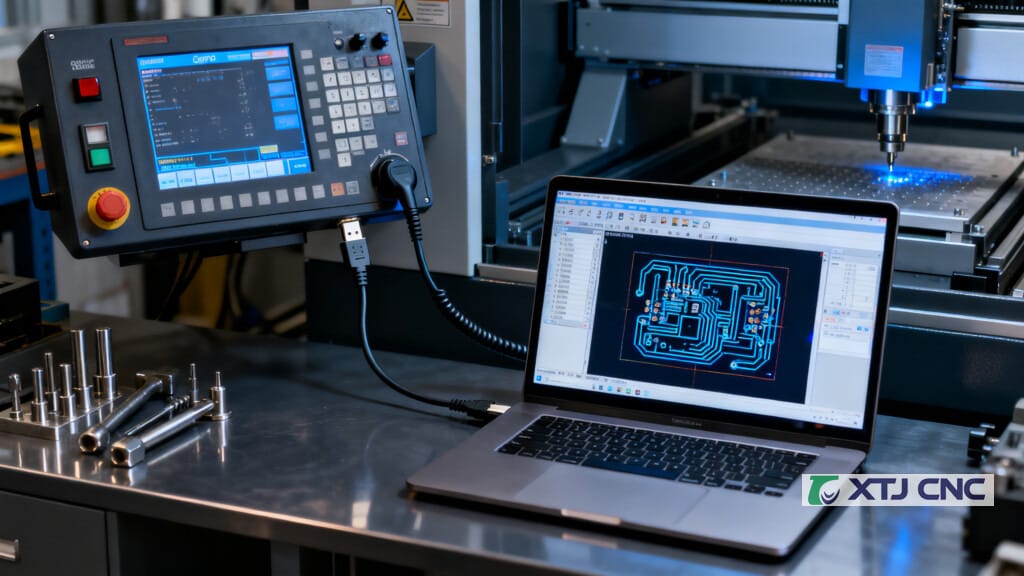
PCB designs are created in EDA tools such as Altium Designer and Eagle, then exported into manufacturing formats such as Gerber. Drill locations are typically provided as drill files (often .xln).
CNC Fundamentals Relevant to PCB CNC Machines (How Motion and Control Work)
CNC technology traces back to the 1940s and accelerated with CAD/CAM and computing.
A typical CNC machine includes:
- a controller (often described as a mini or microcomputer) that interprets program instructions
- motors and drivers that move axes
- a spindle system that rotates the tool
Motion, feed, and spindle control
G-code generally specifies:
- tool motion (where to move in X, Y, Z)
- feed rate (how fast to move through the cut)
- spindle behaviors (often via commands that start/stop and set speeds, depending on the machine)
M-code typically controls auxiliary functions such as spindle on/off, coolant, or tool changes (implementation varies by controller).
What governs accuracy and repeatability?
Precision and repeatability depend on:
- mechanics: rigidity, backlash, spindle runout, linear motion quality
- electronics: drivers, motor type (stepper vs servo), feedback devices (encoders in closed-loop systems)
- software: toolpath generation quality, calibration routines, and compensation strategies
For PCB milling specifically, setup dominates outcomes. Zeroing, tool length reference, and workholding flatness are critical because isolation milling depths are small. Even slight surface variation can cause incomplete isolation in one area and over-cutting (wide cuts) in another.
What a PCB CNC Machine Actually Does (Primary Operations)
PCB CNC machines are often described by what they do to a copper-clad panel. Here are the core operations.
Drilling
Drilling creates holes for:
- through-hole components
- mounting features
- vias (as drilled holes; plating is a separate process for PTH)
Industrial PCB drilling platforms can be extremely fast. Some high-speed drilling machines are cited at over 1000 holes per minute, with drilling positional accuracy around plus or minus 0.025 mm.
Isolation milling
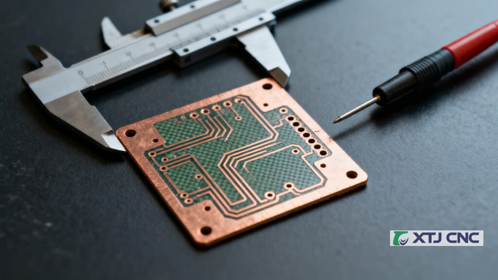
Isolation milling removes copper around intended traces and pads to create electrical isolation without chemical etching. Rather than etching away unwanted copper chemically, the CNC tool removes the copper mechanically around the geometry, indirectly defining the conductive pattern by carving away the surrounding copper.
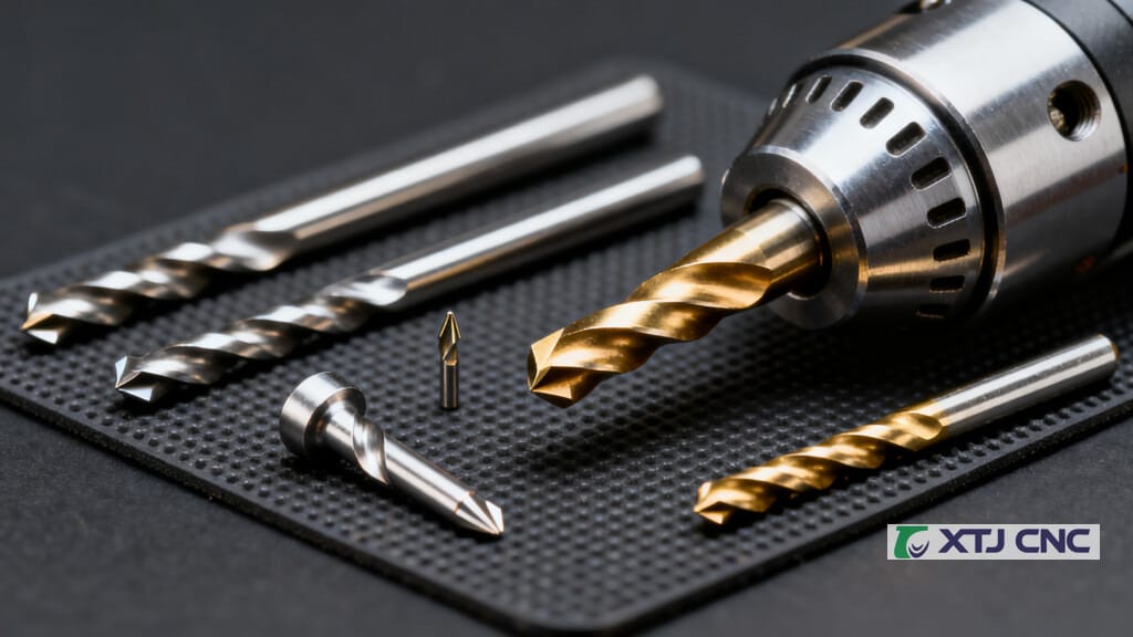
Routing (outline, slots, cutouts)
Routing cuts the final PCB outline from a panel and can also create:
- slots (for connectors or mechanical keys)
- internal cutouts (for displays, clearance, or mechanical integration)
From a design-for-manufacturability perspective, the mechanical layer in Gerber often acts as the blueprint for CNC routing. Ambiguity here is a common cause of scrapped boards, especially when plated vs non-plated slots are not clearly defined.
Practical benchmarks commonly cited in routing contexts include:
- standard routing bit diameter around 2.0 mm
- minimum internal corner radius around 1.0 mm (because round tools cannot make sharp internal corners)
- recommended copper clearance at least 0.25 mm (10 mil) from board edge or cutout edges to reduce burrs/delamination risk
- minimum millable slot width cited around 0.8 mm in some production routing guidance
Engraving
Engraving adds reference designators, labels, logos, polarity marks, and other identifiers. It can also be used for fine surface marking, especially on prototypes where you want clear assembly references.
Double-sided alignment
For double-sided boards, many workflows rely on registration holes and alignment pins. Typically, the board is drilled for registration, then flipped using the same pins so the second side remains aligned.
End-to-End Workflow: From PCB Design to a Machined Board
A PCB CNC workflow is a chain of digital preparation plus careful physical setup.
Step 1: Design (schematic and layout)
Design begins with schematic capture and PCB layout in EDA software. Common examples include Altium Designer, Eagle, and EasyEDA.
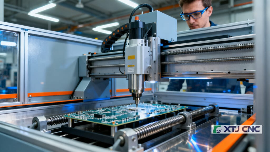
Step 2: Export manufacturing files
Common outputs include:
- Gerber files for copper layers and mechanical outlines (Gerber is the de facto standard)
- drill files for hole locations and diameters (often .xln)
More comprehensive formats like ODB++ and IPC-2581 also exist and can reduce translation errors by bundling more manufacturing intent into a single package, but Gerber plus drill files remain very common.
Step 3: CAM toolpath generation
CAM software translates Gerbers and drill data into CNC toolpaths for milling, drilling, and routing. Examples used in practice include FlatCAM and Autodesk Fusion 360; some ecosystems also use MakerCAM. The post-processor then converts toolpaths into machine-readable programs, commonly G-code (.nc).
Step 4: Machine setup
Setup typically includes:
- selecting bits (drills, V-bits, small end mills)
- setting work zero (X/Y origin) and Z reference (depth control)
- verifying spoilboard/bed flatness
- securing the copper-clad board (tape, clamps, fixtures, or vacuum workholding depending on the system)
Step 5: Machine in a sensible sequence
A common sequencing logic is:
- drilling first (often including registration holes)
- isolation milling
- outline routing last, so the board stays rigid as long as possible
Step 6: Clean, inspect, and verify electrically
After machining:
- clean dust and debris (copper and fiberglass particles are common)
- inspect isolation gaps and edge quality
- perform continuity and isolation checks before soldering
Some users add surface finishing steps depending on requirements and available equipment.
Machine Types and Configurations
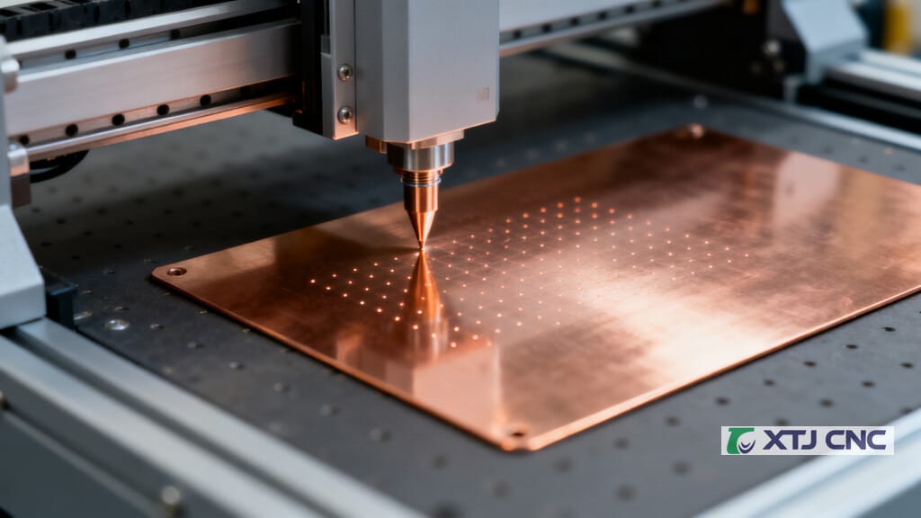
PCB CNC machines vary widely, from desktop routers to specialized industrial drilling lines.
Common configurations
- 3-axis desktop CNC routers adapted for PCB milling
- specialized PCB prototyping mills designed specifically for PCB work
- industrial CNC drilling machines, routing machines, and combined systems in production lines
They differ by:
- work area
- spindle speed capability
- rigidity and vibration control
- accuracy and repeatability
- support systems (dust collection, probes, vision alignment, tool changers)
Spindle speed matters a lot for small-diameter tools. PCB work commonly uses high-speed spindles; published ranges for PCB milling spindles are roughly 30,000 RPM to 100,000 RPM. Higher speeds generally help with small tool diameters and cleaner cuts, assuming runout and rigidity are under control.
Tooling and micro-features
PCB CNC commonly uses:
- tungsten carbide drill bits for holes
- V-bits (for fine isolation geometry) such as very small tips (for example, 0.1 mm at 60 degrees or 0.2 mm at 30 degrees in some hobby/prototyping guidance)
- small end mills for isolation and routing
Because tooling is small, it is also fragile. Tool wear and breakage are normal operating realities, not rare events.
Workholding options (why it matters)
The outline notes that workholding may include clamps (and in practice can also include tape or vacuum fixtures). The goal is always the same: keep the panel flat and immobile so Z-depth stays consistent and drill hits remain accurate.
Height mapping probes are a major differentiator on machines intended for PCB isolation milling. They scan the PCB surface and compensate for tiny flatness variations that otherwise cause inconsistent isolation widths.
Quick Reference
| PCB milling machine market | USD 568.3M (2025) to USD 608.1M (2026) |
| Global PCB market | USD 89 to 91B (2025), exceeding USD 95B (2026) |
| High-frequency materials cost | 5 to 10 times cost vs FR-4 |
| Spindle speed (PCB milling) | 30,000 to 100,000 RPM |
| Drilling accuracy (industrial) | about plus or minus 0.025 mm |
| Drilling throughput (high-speed) | over 1000 holes per minute |
| Routing bit diameter (common) | about 2.0 mm |
| Minimum internal corner radius | about 1.0 mm |
| Copper clearance from edge | at least 0.25 mm (10 mil) |
| Minimum millable slot width | about 0.8 mm |
Advantages
- Faster turnaround than outsourcing: often hours or days in-house versus 2 to 4 weeks typical for production setup cycles
- Good for small runs: commonly cited as cost-effective for 1 to 20 units, avoiding minimum order quantities, shipping, and setup fees
- Full process control: you can tweak a design and rerun immediately
- Cleaner than DIY chemical etching: avoids hazardous chemicals and chemical waste
- Better physical fidelity than breadboarding: milled PCBs resemble the final board in layout and electrical behavior
Disadvantages
- Setup time per design: file preparation, toolpath generation, and alignment can be time-consuming for one-offs
- Milling can be slow on fine designs: removing material incrementally takes time
- Dust and debris: copper and fiberglass dust require cleanup and usually dust collection
- Tool wear and consumable cost: small bits break; replacements add ongoing cost
- Feature limitations: trace width/spacing and hole sizes are limited by tool diameter and machine accuracy
- No plated through-holes on most desktop setups: this is a major constraint for multi-layer connectivity
Practical Examples and Actionable Tips
Example: same-day microcontroller adapter board
If you are building a quick adapter board (for example, a breakout or a simple shield-style prototype), a PCB CNC workflow can let you validate:
- connector placement and mechanical fit
- signal routing and basic functionality
- quick design changes (pad size tweaks, trace reroutes) within the same day
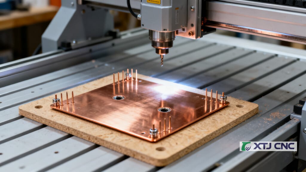
Tips that improve results immediately
- Prioritize flatness: use a surfaced spoilboard, strong tape/fixture strategy, and height mapping if available.
- Keep copper away from routed edges: following guidance like at least 0.25 mm copper clearance reduces burrs and edge shorts.
- Use realistic internal corner expectations: if you need sharp internal corners, you may need design reliefs or different manufacturing methods because routing tools impose an internal radius (often referenced around 1.0 mm minimum).
- Manage tool life: spindle runout should be controlled (a commonly cited target is below 0.01 mm) because runout accelerates breakage and wear on micro drills.
- Separate PTH expectations from drilling: you can drill a via hole, but without plating it will not behave like a production via.
Safety and Maintenance Essentials
PCB CNC machines are still CNC machines: they can start automatically and move without warning.
Key operational safety practices commonly emphasized in CNC manuals include:
- wear OSHA-approved safety glasses, safety shoes, and ear protection
- secure hair and avoid loose clothing/jewelry
- keep the work area well-lit and uncluttered
- clamp work properly; do not reach into the machine’s motion envelope until it is fully stopped
- power off and use lockout/tagout before electrical maintenance
- ensure proper grounding
Dust control is also a health and reliability issue. Fine fiberglass and copper debris can irritate lungs and contaminate machine components, so dust collection and routine cleaning are not optional for consistent performance.
For longevity, preventative maintenance matters. In industrial contexts, control PCBs (the electronics inside CNC systems) can last 15 to 20 years with good care, while moisture, dust accumulation, vibration, high temperatures, and power surges are common causes of premature failure. Refurbished replacement parts can sometimes reduce costs significantly (figures as high as 75% savings versus new are commonly cited for certain industrial components).
When a PCB CNC Machine Makes Sense
A PCB CNC machine is a computer-controlled subtractive fabrication tool that drills, isolation-mills, routes, and engraves copper-clad laminates to produce functional PCB prototypes quickly and repeatably. It shines when iteration speed, in-house control, and “same-day hardware” are the priority.
At the same time, it is not a full replacement for professional PCB fabrication for multi-layer boards, plated vias, or high-reliability requirements. The best results come from matching the method to the goal: CNC for early prototypes and mechanical validation, then qualified fabrication for production-intent builds.
If your team is evaluating PCB CNC capability for prototyping or small-batch support, treat it like any precision manufacturing investment: focus on rigidity, spindle quality, dust control, calibration workflows, and the real total cost of ownership (tooling, software, maintenance, and training).
Frequently Asked Questions
What does a PCB CNC machine do, exactly?
It converts a digital PCB design into CNC toolpaths and then machines a copper-clad laminate. Typical operations include drilling holes, isolation milling (removing copper around traces/pads), routing the board outline and cutouts, and engraving reference marks.
Is PCB CNC machining additive or subtractive?
Most PCB CNC fabrication is subtractive manufacturing: it removes material (copper and sometimes substrate) to create the circuit pattern, holes, and outline. This contrasts with additive approaches like printed electronics or some forms of 3D printing.
Do PCB CNC machines use G-code?
Yes. Toolpaths are usually post-processed into G-code for motion commands, with M-codes used for auxiliary functions (spindle/coolant/tool-change behaviors depending on the controller).
Can a PCB CNC machine make plated through-holes (PTH)?
Drilling is easy; plating is not. Most desktop CNC PCB workflows cannot create PTH without additional plating processes and equipment. That’s a key reason CNC prototyping is often best for 1 to 2 layer boards without plated vias.
How fast is a PCB CNC machine compared to outsourcing?
In-house CNC prototyping is often completed in hours or days. Outsourcing commonly takes weeks (often cited as 2 to 4 weeks for standard production setup and fulfillment), though expedited services can be faster at a substantial premium.
What materials can it cut?
Commonly FR-4 copper-clad laminate. Higher-frequency laminates like Rogers and ceramic substrates can be used depending on machine setup and tooling, but they are often 5 to 10 times more expensive than standard materials, so process control becomes even more critical.
What are the biggest factors affecting quality?
Workholding flatness, Z-depth control, spindle runout, tool condition, and correct CAM settings (feeds, speeds, depths). For isolation milling in particular, flatness variation across the board is a frequent root cause of inconsistent trace isolation.